I have tried on several occasions to design a wooden clock with a Swiss Lever Escapement, but so far none has been really successful. The problem is that the lever requires a Balance wheel and Spring for it to work and I can not get a wooden spring to work successfully.
I developed Clock 29 as a 3D printed clock a couple of years ago and this used a plastic spring but in association with a gravity escapement, so as a development project, the design of the Minute engine is to look at some of the variables that would need to be resolved for a clock utilising a Swiss lever movement to function
 |
| Typical Swiss Lever Escapement |
Using the arrangement of the parts in the illustration above, which is standard for a typical Swiss lever escapement, the next decision to make was the type of drive train to use and what the power source would be. The power source was straight forward as I wanted a small compact design so it would have to be a steel clock spring that would allow the engine to run for several hours.
From this point it the design of the gear train would hinge on the requirement to have as an output an Indicator Hand that would revolve once every minute. Initial testing of the oscillating frequency of the Balance wheel and spring suggested a gear pairing of around 10:1 for the first stage and then followed by a 64:1 would give a relatively simple 3 stage gear train with 10:1, 8:1, 8:1 using three large wheels with 64 teeth and two pinions with 8 Teeth and 1 Pinion with six teeth.
Video on YouTube https://youtube.com/user/woodenclocks58
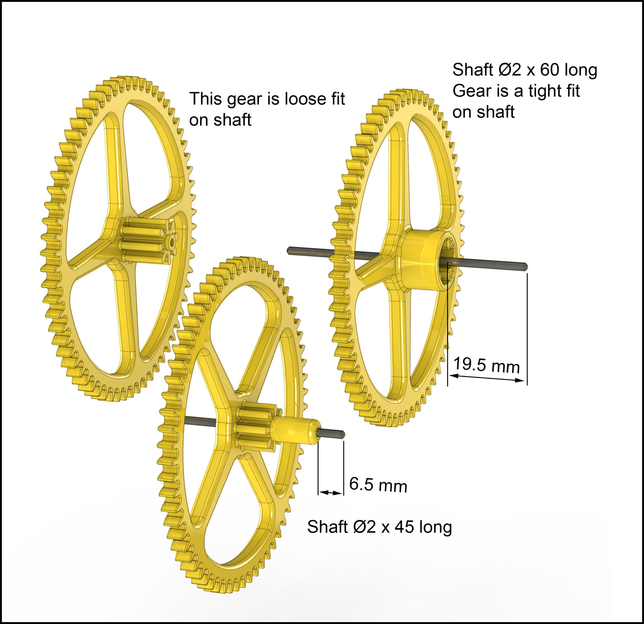
 |
| Gear train |
This is the arrangement of gears that I finally settled on leaving only the connection to the Spring used to power the device and a frame to hold it all together.


The two images above show the completed Minute Engine and how the drive power is fed to the gears through the back frame.
The Engine, as designed here will run for around 4 hours on a complete wind is accurate to around 1 minute per hour. To improve on that accuracy more development will be needed on the Spring and the Balance wheel. The design of the balance wheel includes the provision for the fitting of up to 12 Ø4 diameter steel ball bearings around the periphery and in this case, I adjusted the number used to just 2 balls, 1 positioned at the 12 o'clock position and one positioned at the bottom in the 6 o'clock position.
This ran to within 45secs per hour, accuracy wise this was as good as I could achieve with this current arrangement
To improve the accuracy further, work is needed on the Balance Spring to speed up the running slightly to get to a more reasonable 10 seconds/hour which for a plastic 3D printed clock is probably as good as you could ever expect.
It was never my intention to create an actual clock from this exercise, only to use it as a means develop a working Swiss Lever Escapement and then use that as the engine to drive a complete 3D design for making by 3D printing. As a consequence of this, I inadvertently made it rather difficult to incorporate the Minute hand and Dial that would be essential to gauge the accuracy of the running clock, the subsequent compromise was the introduction of a Minute hand at the back of the gears and a short section of Dial mounted on the Back Frame, not ideal but I was able to use it to measure the accuracy of the running clock.
Building the prototype
Should you wish to make your own you can download the STL files from any of the sites listed below.
I would start with the main gears and make sure that the 3D prints are clean with no strings or bumps that could prevent the smooth running of the gear train.


There are 5 pins to be fitted to the frame as shown above before attempting to fit and of the gear sub-assemblies, these will all be a tight fit in the frame. Again lightly oil the shafts prior to fitting the gears to them.

Start by fitting the 3 large 64 toothed gears and the small 6 toothed gear into the front frame.

The spring I used in this engine is a Loose Loop Triflex Clock Spring 6mm wide x 0.4mm thick x 1000 mm long, purchased from Cousins UK part number. The ends will have to be modified as shown above by heating the ends to red heat and allowing to cool slowly. This will soften the ends and enable them to be reworked so that they can fit onto the Cas and drive printed parts.

With the spring-loaded into its case and the drive component fitted into the centre of the spring, offer up the Spring case and slide the drive over the end of the shaft and push it home. You may have to slowly rotate the Spring Case Anti-clockwise to get the sprockets on the drive to engage and allow the assembly to be pushed right home flush with the back case.

Now for the tricky bit, whilst holding the spring case in place fit the Retaining ring over the Spring case, whilst swapping fingers so you never let go of the spring case, and then having got the retaining ring fully over the Spring case make sure the window in the side is near the bottom rotate the ring clockwise to the stop to finally have the spring locked in place. The last step is to fit the Sprig loaded Pawl to the bottom of the ratchet using the two pins on the frame beneath the spring. To fit the spring locate the left hand hole over the left hand pin and squeeze together the other ends so that the very end of the Pawl pokes through the window in the Spring Retainer and engages the Ratchet.

Start by fitting the Escape wheel to the end of the shaft that contains the 6 tooth gear on the other side of the frame, this should be a tight fit on the shaft. Follow this by sliding on the Lever and adding one of the endstops to retain it in place, this to be a loose fit on the shaft.
The Spring shown here in purple should be fitted along with the Spacer shown in blue to the back of the Balance wheel and orientated to the Balance wheel using the short pin. The outside end of the spring has a boss that should be fitted onto the short pin in the Frame and held in place with another Endstop.
Now fit the two ball bearings to the Top and Bottom positions on the balance wheel and finally fit the Balance wheel to its shaft securing with another Endstop. This Balance wheel / Spring sub-assembly should be a loose fit on the shaft.

That's it the Minute engine is complete and should run for a good 4 hours between winds.
Parts and materials required
1 - I used ABS for all of the parts and printed all the parts with 0.2 layer thickness and 50% fill, the exception to that was all of the smallest parts printed solid.
2 - The Mainspring was a Loose Loop Triflex Clock Spring 6mm wide x 0.4mm thick x 1000 mm long, purchased from Cousins UK Part number 6401000LL. Hopefully, the description is enough for you to source the same spring locally.
3 - All the shafts were made from Ø2 diameter Silver Steel or Drill Rod as it is termed in the US. A 300mm or 12" length should be sufficient.
4 - A couple of Ball bearings to weight the Balance wheel Ø4 mm diameter or Ø3/16"
5 - You can use this JPG files for the Dial insert that runs in an arc around the top of the back frame.
6 - STL files for you to build your own Minute Engine can be downloaded here.
7 - If you use Solidworks you can download the Spiral spring file here