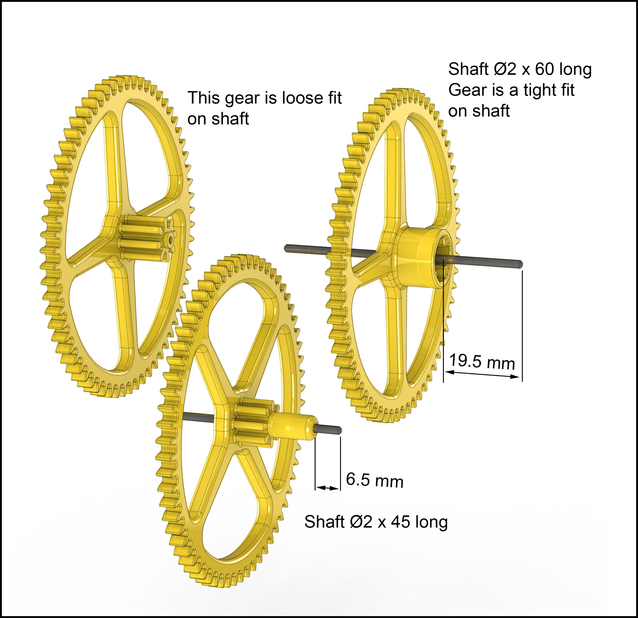
A clock's Minute hand rotates once for each hour and the Hour hand rotates once for every 12 hours, so a ratio of 12:1 reduction is required from the gear train that connects the two hands. To do this I normally use two pairs of gears with 3:1 and 4:1 ratios giving the total reduction of 12:1 required.
A design journal for Wooden clocks, with occasional thoughts on side issues related to clock design, materials, mechanisms and automata in general. To see all the clocks visit the main website at www.woodenclocks.co.uk
Search This Blog
Thursday, 24 February 2022
Daisy wheel motion for clocks Hour Hand
Friday, 14 May 2021
The woodenclocks weight drive - Alternative designs.
Wooden clocks are driven, in the main by a single drive weight hung from a cord wrapped around the Drum, and it is this type of drive that we are going to look at in this article.
In the first clock, I ever built I used a piece of granite with a hook screwed into the top, it worked well but did not sit well with the traditional image of a clock. For a long time, my plans just included a simple Brass weight which looked the part but, to be honest, wasn't necessarily very easy for woodworkers to construct, so began a series of designs using fabricated parts and some proprietary items.
Design 1 uses a Plastic Tube with wooden endcaps and a threaded rod with nuts at the top and bottom to hold the whole together. I wanted the weight to be attached to the cord simply but a screw-in hook was not going to work with the threaded rod sticking out the top of the weight. This led to the design shown below that uses a Bowline knot on the end of the cord and a wooden hoop holding the nut inside.
With this Tubular construction, the weight is added to the Tube before it is fully assembled. My favourite weight type is of course Lead as it is the densest material that you can practically use and it comes either as Lead shot or as cylindrical weights of the type generally used for Sash type windows.
An alternative to Lead is to use Ball bearings, if bought in the form of 'Catapult shot' they will be much cheaper.
I struggled for a while to find the correct type of Knot to use to hook up the weight to the clock. The problem was that all the knots I was trying would slip until I came across the Bowline knot which is shown here, a bit more complicated to tie but once done it works a treat with no slippage.
Monday, 21 September 2020
A design for a Minute engine
I have tried on several occasions to design a wooden clock with a Swiss Lever Escapement, but so far none has been really successful. The problem is that the lever requires a Balance wheel and Spring for it to work and I can not get a wooden spring to work successfully.
I developed Clock 29 as a 3D printed clock a couple of years ago and this used a plastic spring but in association with a gravity escapement, so as a development project, the design of the Minute engine is to look at some of the variables that would need to be resolved for a clock utilising a Swiss lever movement to function
![]() |
| Typical Swiss Lever Escapement |
![]() |
| Gear train |
Thursday, 14 February 2019
A chart for discovering Woodenclocks features.
There was a time, not so long ago when I could remember the details of all my clocks, but sadly there are now so many that it becomes progressively more difficult to do that. So if I am having trouble remembering details of all the clocks I realised that it must be twice as hard for you to make choices of the clock you want to make for yourself.
With this in mind, I have put together a chart that tries to list all the relevant information about each one to make your choice a little easier.
The chart is actually a PDF file that was created in Excel with each clock listed in the first column and the relevant feature information in the following columns.
The first column, Made From indicates the material that the clock was designed to be made from, the great majority are designed to be made from hardwood and an earlier post on that topic gives you some help choosing the most suitable for your clock.
The choice, of course, is not limited to just wood, you can construct these clocks from metal or plastic as well, and many people have already done this, but wood is the most popular choice, after all, it is a wooden clocks website. There are some exceptions to this, and these are the 5 clocks designed and intended to be made using 3D Printing. These clocks are not supplied with DXF files for CNC machining but use STL files instead for use with a 3D printer. These were originally intended for use as prototypes for me when developing the clock designs, but have proved to be popular so they are now included in the portfolio of clocks.
The third column Units indicate whether the clocks were designed in mm or inches, all clocks from Clock 9 onwards are dual-dimensioned in both mm and inches.
The fourth column indicates the degree of difficulty in building the clock. This is usually down to how complicated certain parts or assemblies are actually to make If a clock can be made entirely using the CNC machine and hand tools then it is easy. Even Easy clocks are not really simple, clocks to work continuously and accurately still take a lot of time and patience on your part so be prepared for a challenge.
With the Intermediate category, we have clocks that are a little more complex and will have bearings and ground steel shafts to provide more precision in the clock. You may also need to find some slightly more difficult assembly operations that need to be carried out.
When you get to the Hard clocks it's just more of everything that the others have and you probably need some better equipment like a lathe and pedestal drill.
There are a couple of very hard clocks that both have quite complicated build requirements and lots of fine adjusting to get the clocks to run and keep running.
The Longest Part column gives you some indication of the size of the finished clock, in each case, it will be the length of the Back frame of the clock.
The Pendulum Length column gives you an indication of how fast the clock will tick, a length of 990 mm will do a tick-tock in 2 seconds, and a 250 mm length will do it in 1 second. So the shorter the pendulum the faster the rate. An earlier article on the subject of Pendulums explains this in more detail, see the link below.
The Weight needed to run the clock continuously will vary dependent on the quality of the build, the more friction in the working gears the more weight you will need. My clocks being prototypes are generally speaking a little rough around the edges because of the change that gets made to the parts to get them to work in the first place. So you may well find that your clocks will need less weight to keep the clock running, you can only find this by experimentation.
The next column lists the Run Time, it is based on my experience with the building of the prototypes and can only be used as a guide, there are a lot of factors that can affect the running time, not least of which is the height of the clock above the floor, or more precisely how far the main weight will drop from fully wound to when it hits the floor. For the times listed in this column, I had the clocks mounted so that the centre of the dial was 1500 mm above floor level if your clock is mounted at 1650 mm then you will increase the running time by 10%. There are several ways to increase the run time, you can add a simple Pulley arrangement to double the run time but this will also require you to double the weight. The letter P adjacent to the run time in this column indicates that this clock was designed with a pulley built into it. There are other ways to increase run time, one is to reduce the diameter of the Drum so that less cord is let out with each rotation of the drum, but again this doubles the weight.
The final column Escapement tells you what type of Escapement is used to control the ticking of the clock, the simplest and most common escapement is called The Graham named after its inventor, this is a deadbeat type of escapement that halts the rotation of the Escape wheel at each Tick and Tock, a simple design that works really well but not the most efficient design because of the friction involved. The Gravity Escapement overcomes most of the areas of friction experienced in the Dead beat design, the design used on these clocks which I call the Woodenclocks Gravity Escapement was designed specifically for use on these woodenclocks it is a more complex escapement but it does result in more efficient clock design. The Verge and Folio is one of the very first designs to be used in the very early clocks, it is visually quite interesting but not very accurate. Then there is the Grasshopper a very elegant design invented by John Harrison back in the 18th century, it is actually quite hard to get it going, and needs a fair amount of tinkering. Finally, the Flying Pendulum is definitely one of a kind wonderful to watch it work but not very accurate.
References
An Illustrated version of the index can be found here.
https://brianlawswoodenclocks.blogspot.com/2013/01/materials-for-wooden-clocks.html
Simple Pendulum
http://brianlawswoodenclocks.blogspot.com/2014/03/simple-pendulum.html
Thursday, 8 February 2018
How to cut Clock Frames on a smaller CNC table.- Part 2
This time I shall look at a single method that can be used to simplify the operation using the Cut2D software from Vetric
To start this we need fill out the Job Setup Dialogue in the top left hand corner of the screen, the blank size and thickness to be used , along with the Z datum and the XY Datum which importantly should be set in the bottom left corner of the blank, the red dot marking the spot.
Having completed that we can generate the first tool path to drill the holes in the Spoil board, I have used a Ø3mm cutter for this, same as is used for all the other cuts. These two holes will be used later to fit location pins into when the blank has to be moved. Save this tool path and generate its gcode so that you can drill the holes in the Spoil Board later.
We do this using the Tool path Tiling Manager as indicated below, this brings up the dialogue box shown on the left. We need to select 'Feed through in Y' under Tile tool paths and the Tile Height to half the blank length. The first tile is shown as the bottom half of the blank and is marked T1, clicking on the Active Tile box changes it between Tile1 and Tile 2.
You need to keep this Dialogue box open through the next steps.
With that preparation complete return the blank to the top of the spoil board and fix in position with the bottom left hand corner on the Datum XY mark and fix in position, zero the Z height to the top of the Blank if necessary .
Now load the tool paths for Tile 1 and cut the holes and profiles.
With that complete release the blank, fit two dowels into the two holes drilled into the spoil board and locate the blank over them and fix the blank down in its new position, load the tool path for tile 2 and complete all the cuts.
Thats it your done and hopefully have a perfect Backframe completed.
Thursday, 1 February 2018
How to cut Clock Frames on a smaller CNC table.
It did, however, make me realise that during all the times I struggled to cut those clock frames I had found a number of different ways to get around the problem so this article will describe 4 of those ways.
None of these is really simple and all require that you are able to use CAD software to manipulate the files, the first two can be done on 2D CAD using the DXF files whilst the last two require the use of 3D CAD to work with the STP or IGS files.
Method 1 - Vertical displacement of the Blank.
The first step is to download the DXF files and load it into your CAD software.
These next two methods require the manipulation of the 3D CAD files to cut the IGS or STP files into segments and then generating the DXF files from those new parts.
The files are loaded into your 3D software and then cut into 3 parts using a Z shape spline or surface to generate a Half Lap joint on the ends of the parts.
After the 3D model has been cut into the sections these sections are used to Generate new DXF files that can be used in the CAM software to generate the gcode for cutting the parts.
Method 4 - Simple split with Biscuit.
In the 3D model cut out a pocket in the back of the frame between two holes and then cut the frame into two halves, see below.
With this method, it is also possible to make the changes in the 2D files by drawing the pocket and the split lines onto the 2D drawings files and creating two new DXF files that are used to generate the gcode.
Sources of 2D and 3D software
If you need 2D/3D CAD software you can try these sources
Autodesk Fusion 360 2D/3D CAD free versions available.
Free CAD CAM software for free software
Vetric Cut2D Excellent for CAM $149 / £110
Monday, 22 August 2016
Using a Balance wheel and Spring to regulate a wooden clock movement.
I had wondered for a while if it would be possible to regulate a wooden clock with a Balance wheel and spring instead of using a Pendulum. I'm not at all sure that it actually offers any advantage other than being far more compact, and that, of course, is where the original designs for this type of regulation originated.
The Lever escapement invented by Thomas Mudge in 1750, has been used in the vast majority of watches since the 19th century, despite its popularity it does have some drawbacks, the main one being that there are several points where friction occurs, so the incorporation of a gravity escapement could help overcome that when used in a wall mounted wooden clock.
Now I can start to look at a complete clock design using this concept to ensure that it would actually work in practice.
The action of the escapement is a little difficult to understand just from the video, but the following notes should hep.
This is the view onto the Backplate of the new clock design with all the main components identified.
Position 2: The Gravity arm has now given its impulse to the Impulse Finger on the Balance wheel and the tip of the Gravity Arm is about to push on the trigger.
Position 3: The Gravity arm has now pushed the Trigger to release the Escape wheel, this must happen before the fork on the end of the Lifting Lever reaches Lifting Finger otherwise the mechanism will seize up.
Position 4 The Gravity Arm is now being pushed back by the clockwise rotation of the Escape wheel, the Lifting Finger is causing this by pushing against the fork in the end of the Lifting Lever.
Position 5 As the Gravity Arm is pushed back the Trigger is also moving back to its locking position ready to stop the rotation of the Escape wheel any further. The Balance Wheel has now reached its furthest Anti-clockwise rotation.