Search This Blog

Tuesday, 9 September 2014

Printing clock plans using PDF and DXF files

If you are going to cut out the gears and the other components for the clocks using a Scrollsaw or a Bandsaw you are going to need a 1:1 scale print of the part that can be stuck onto the face of your wood so that you can accurately cut around the profile.There are basically two ways to achieve this, either from the PDF file of the drawings or from the DXF file containing the all of the flat 2D parts in the clock.
The first method is probably the easiest but is a little untidy because the drawings contain dimensions and notes that will be picked up in the selection process and printed along with the outline of the part. To avoid this you can use the second method which is to make the selection from the DXF or the DWG file.

Printing a selection from the PDF file of the drawing.

You can print a selected area of a PDF file to scale if you are using Adobe Acrobat Reader or Foxit Reader.
Open the file and go to 'Edit '- 'Take a Snapshot' or 'Home' - Snapshot @ and  click on this (see picture below)  and then draw a box around the area to be printed (See the second picture)
Now click on Print.
In the dialogue box make sure 'Selected Graphic' is ticked and that the Page Scaling is set to 'Size' or 100%. Now click OK and it should print the highlighted area to size.
Note this will only work for Clocks 1,2,4 and 5 as these have no protection added to the PDF files.
For all other Clocks, you will need to purchase unlocked PDF file for it to work.


Printing a selection from the DXF or DWG file of all the 2D parts.

I would recommend that you get a free copy of DWG TrueView from here http://www.autodesk.com/products/dwg/viewers#  download and install on your machine.

Load the DXF file using File - Open  and then go to
View - zoom - Extents. This puts the whole drawing on the page.
The file contains several layers that hold the Text and Grid, these can be switched off by using the Layers menu (see below)
To hide layers click on the light bulb beside each layer that you don't want to see.


Now goto File - Plots to bring up the Plot/Print menu.


Now fill out sections of the new window that appears.

In the Printer/Plotter click the down arrow and search for your printer, then click on it.
For Paper size click on the paper box and search for your paper size then click on it.
In the Plot Area click on the button below the 'What to Plot' and select 'Window' now another 'Window' button appears, click on that and it takes you to the drawing.
This allows you to select around the gear or other part you want to print out, so left click and pull a window around the part and left click again to complete.

Back in the Plot dialogue box make sure fit to paper is unticked and the scale is set to 1:1.
Also tick centre the plot so that the printed part is in the centre of the printed page.

If you want to see a preview of what you are about to print click on the Preview button.


Finally click OK on the bottom line to print.


Tuesday, 11 March 2014

Simple Pendulum


The Dutch astronomer Christiaan Huygens is credited with first suggesting the use of a pendulum in a clock to regulate its movement. Pendulums are useful because they have an extremely interesting property: The period (the amount of time it takes for a pendulum to go back and forth once) of a pendulum's swing is related only to the length of the pendulum and the force of gravity. Since gravity is constant at any given spot on the planet, the only thing that affects the period of a pendulum is the length of the pendulum. The amount of weight does not matter. Nor does the length of the arc that the pendulum swings through. Only the length of the pendulum matters.
The pendulum used in my wooden clocks is in technical terms a simple pendulum, in essence, a mass suspended from a fixed point so that it can swing back and forth under the influence of gravity.
Real  pendulums have the mass fixed to the end of the pendulum rod so the actual centre of the mass of the whole pendulum is, in reality, a little closer to the pivot as shown in the diagrams below because the rod itself has some mass.
The formulae for calculating the period of swing is -

pendulum period

What is probably more useful is to work out the Length to the centre of mass so that we can set the initial length of the pendulum, to do that use-

 pendulum length

where T = Period of oscillation, i.e. time to swing back and forth.
             L = Length from Pivot to the centre of mass.
             g = Acceleration due to Gravity meters/second^2   (9.81m/s^2)
             Pi (π) = 3.142

For most of my clocks I use a 2 seconds pendulum i.e. the time to swing back and forth is 2 seconds.
To work out the length of the pendulum from the pivot point to its centre of mass use above formula.
      
L=2²*9.81÷(4*3.142²) = 0.993 meters

For a 1 second pendulum used on Clocks 9,12 and 14

L=1²*9.81÷(4*3.142²) = 0.248meters


Links to Useful Websites:

Useful Formulae for Simple Pendulum calcs
History of the Pendulum use in clocks
http://en.wikipedia.org/wiki/Pendulum_clock#Atmospheric_drag

Thursday, 13 February 2014

Designing a new Gravity escapement


History
The accuracy of a clock is dependant upon rate at which the pendulum swings and this can be adversely affected by friction at the numerous contact faces throughout the drive train and the escapement mechanism. The problem was particularly pronounced in Turret clocks where the drive train was needed to drive large hands subjected to weather conditions and other natural variables such as pigeons roosting on the hands.
The solution to the problem was to separate the drive train from the Escapement, in this way the drive train can be driven by a weight so large that it can propel the hands no matter what the adverse loading conditions, but the escapement was driven by a secondary constant load fed only indirectly from the main drive. This type of drive was called a Gravity escapement.
The way this is done is to have the impulse to the Pendulum provided by a separate Gravity Arm that once lifted, and then freed from its stop, applies a constant impulse to the Pendulum without interfering with the free swing of the pendulum. 
The earliest Gravity escapement was designed in 1766 by English clock-makers Thomas Mudge and Alexander Cumming. 

This idea had some problems with tripping of the locking function under differing loads, this problem was finally solved by the great British horologist and lawyer Edmund Beckett Denison with his invention of the famous “Double three-legged gravity escapement” incorporated in the clock mechanism of Big Ben. To this day it regulates the running of the Great Clock of Westminster with extreme accuracy and reliability.  


There is still a problem with this approach though, as the pendulum is require to unlatch the Gravity Arm at the end of its swing, this has to be done with the latch holding back the full loading of the driving train, so the frictional loss's at that point can be variable over time and so effect the accuracy of the clock.
James Arnfield devised a way to overcome this variability by redesigning the Escapement so the unlatching was carried out by an Unlocking Arm rather than the Pendulum, the Pendulum was left with the less arduous task of unlatching the Gravity Arm.


Design
When considering what design of Escapement to use on one of my new clocks , the Arnfield design was obviously favourite because of its simplicity, I was only concerned  the Gravity Arm may not get back to its rest position in time to stop the Escape wheel, which was being powered around by the drive train. This was a particular problem for me as I wanted to use a 15 toothed Escape wheel to keep the rest of the drive train simple.
The solution I adopted is shown in the sketch below and the video.

I have shown below some of the ideas from my sketch book, these were jotted down over a couple of days, this first one starts with a trigger mechanism used on a crossbow, it is capable of holding back high loads but is easily triggered, which is just what we need.


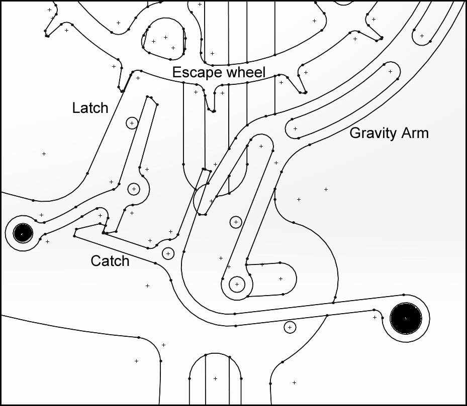
This sketch shows the principal applied to the side of the Escape wheel, a latch engages the a tooth on the escape wheel and the latch itself is supported by a catch that can be easily knocked aside by the the end of the gravity arm, the lower arrangement being preferable with the catch positioned further from the pivot.


This sketch has the latch moved to the bottom of the escape wheel which is more convenient for picking up the end of the Gravity arm.


This is the concept laid out in 2D CAD, it actually looked quite promising at this stage, but later analysis showed that the latch would be pushed around so far before it could release the Escape wheel that the was a god chance it would not get back again before the next tooth arrived.


Time for a re-think, we need the latch to return much more quickly and with more certainty so its time to try a latch with multiple teeth.


This gives you an idea of the way I'm thinking but it needs more resolution how it is to interact with the Gravity arm


This is starting to look more promising, with multiple arms on the latch, one will always be in position to catch the next tooth.


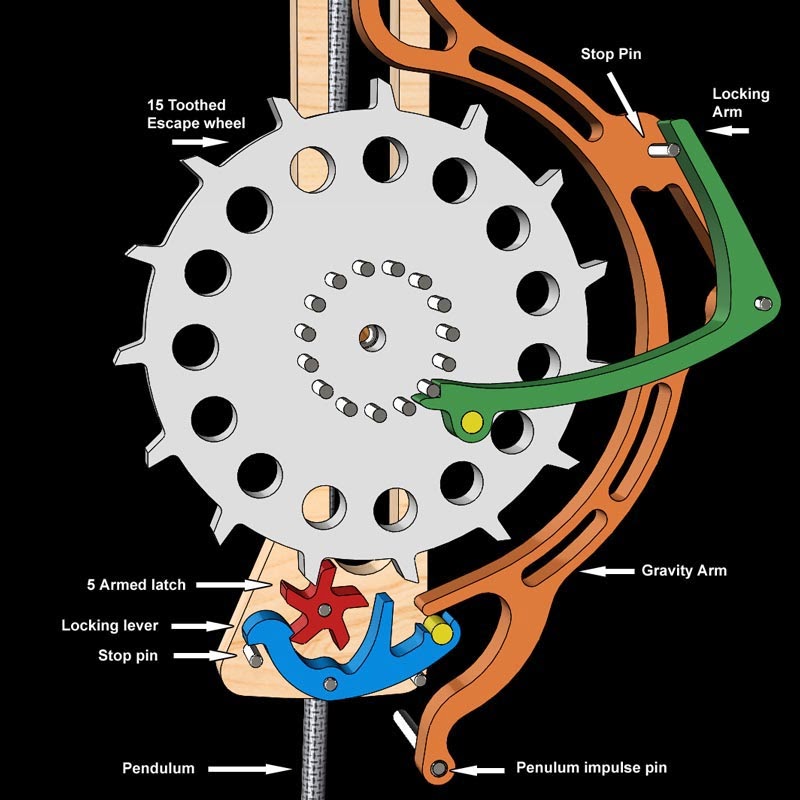
Transferred into 2D CAD it was found that 5 arms on the latch would be optimum for this arrangement, so it is this concept was moved into 3D CAD and animated.


In this design the red Five armed Latch holds back the white Escape wheel whilst being held itself by the blue Locking lever. This is released by the Gravity arm after it has been released by the Pendulum at the end of its anti clockwise swing, the Gravity arm now swings down carrying the Pendulum with it, it hits the blue Locking lever releasing the  red 5 armed Latch to allow the Escape wheel to run free, pushing on the green Locking arm to reset the Gravity arm.
The pendulum plays no part in this unlocking, only the Gravity arm.
The red Five armed Latch rotates to bring the next locking face into play before the next tooth on the Escape wheel can get past, the Five armed latch in the meantime is itself locked by the return of the blue Locking lever under the influence of gravity, assisted by the brass weight positioned at the back of the locking lever.

http://youtu.be/Jndb4gSwWvw


The next step is to build a prototype to ensure that the design really does work, and if that is successful incorporate the design into a clock.

Thursday, 21 February 2013

Gear design software

Following from the last post the following list of sites offer Gear profile generators to create the gears for you.


http://woodgears.ca/gear_cutting/template.htm

This first Gear template can be used either on line or you can purchase a fuller more feature rich version for use on your PC. The output is to an HPGL format that can be used for direct printing .
One of the benefits of the paid for version is that it can export to DXF format


Gearotic
This software will provide templates for all manner of gears, ratchets and clock escapements along with the facility to adjust the profiles. Output as DXF files. This is not a free program but you can download a demo version to try it


http://www.emachineshop.com/machine-shop/Download/page100.html

eMachineShop is a Free 2D drawing package with a module for drawing gears, easy to use, you simply add the basic gear parameters and it draws the gear which can then be exported as a DXF file.
The program is free but unlike the first two programs it lacks the facility to see to the main gear and the pinion on-screen at the same time.


http://www.forestmoon.com/software/GearDXF/
Simple Free program , input gear parameters and then save as DXF.


CycloidalGearBuilder
This is a program to generate tooth profiles in an epicyclic form rather than the more generally used involute form. For a description of the difference see the following:-

Comparison Between Involute and Cycloidal Gears
The output from this program is in DXF format and can be viewed in a browser.

Wednesday, 20 February 2013

Gear Train design for the wooden clock


The gears used in all of my clocks have geometry based on the standard gear profile formulae with some adjustment to the tooth profile to thin them down a little to make it a bit less sensitive to the inaccuracies inherent when using hand cutting methods to produce them.
When designing clock gears I generally use the metric system to define the teeth but both metric and imperial can be used interchangeably. The chart shown below shows the formulae I use for gear calculation.


For the gear teeth to engage with each other they must both be calculated using either the same Diameter Pitch (DP) or the same Module these two terms relate to the way the teeth are spaced around the Pitch Circle Diameter (PCD). You can see from the chart below that as the Mod increases so does the size of the tooth, and visa versa for the DP.
If you are working with metric dimensions you will use the MOD and if you are working in imperial dimensions you will use the DP.
Generally speaking, if you are building a wooden clock then you will be using Mod 1.5 or above.


Once you have decided on the DP or Module you are going to use that to calculate all the other features using the formulae in the chart at the top. Both these charts come from the Technical section of the HPC Gears catalogue 
There are two main gear trains in a clock, the minutes train that requires a total ratio of 60:1 this runs between the shaft carrying the minute hand and the escapement wheel. The escape wheel normally turns once a minute and it connects through the train with the shaft holding the minute hand, which turns once an hour, hence the 60:1 ratio.
The second train runs between the minute hand and the hour hand which requires  12: reduction. This ratio normally has to 2 sets of gears with ratio's of 3:1 and 4:1 and the centre distance of each are normally the same as the gears are mounted on the same pairs of shafts, I always use a 8 teeth and 32 teeth pair along with a 10 teeth and 30 teeth pair, as it allows the shafts to be shared.
With the 60:1 ratio there are many more options open to you and will to a large extent depend on the design you are trying to achieve, so I must leave that up to you to decide. Having said that a simple set of 3 gears using 3 pair sets with ratio's of 3:1 4;1 and 5:1 works quite well as when multiplied together they will give you a 60:1 ratio.
Having decided on the  gear arrangement I normally try to determine the Module value I am going to use and that relates to the size of the gears I want. To determine that I would normally work out on CAD or on paper what size I want the largest gear to be, so in my case this is usually a 60 tooth gear. As an example I have decided the gear needs to be about 125mm (5ins) diameter so from the chart above I can work out a value for the module.
Module = Outside Diameter mm / ( Number of teeth +2)
This gives a value for the Module of 2.016 so round that down to 2.0 and you can now use that value to calculate the sizes for all of your gears.
If you are an organised person you would use a spread sheet to enter all your values to work out the relevant gear sizes, I never got round to doing this so finish up working them out on a calculator.
The chart below shows a typical gear pairing for a 3:1 gear ratio and a Module of 2 using a 60 tooth and a 20 tooth gears. The tooth thickness is slightly less than the normal 50% of the CP value I have used between 44% and 48% of that value depending on what looks to work best in the CAD simulations.


There is another section of the Gear train that has not yet really been mentioned and that is how power is transferred into the system to get it to start ticking. Mostly this is going to be through a weight attached to a cord wrapped around a barrel on the drive shaft. The Drive shaft can be the Minute shaft but this is generally not a good idea as it is going to apply a very high load to the shaft which will eventually lead to early wear to the shaft and bearings so I recommend we use a second more robust shaft to carry the load from the Drum to the Minute shaft. This is shown in all the illustrations below.
This has another advantage as well which is to increase the run time of the clock, introducing a ratio between the two connecting gears of around 2 to 1 double the run time. You can run your own changes on this to increase the run time even more. Do remember that by doubling the run time you also need to double the weight. 
The problem with this is that at some point you will need to rewind the clock as the weight will hit the floor and stop the clock. There are a couple of ways to do this and the first is to introduce a Rachet arrangement shown in the illustrations below.


This illustration with the back of the clock removed shows the type commonly used, it consists of a Ratchet and a Pawl where the Pawls move under gravity to lock into the ratchet at the top, this type needs no springs, so it is fairly simple.
What it does is effectively disconnect the drive when you turn it backwards so that you can rewind the clock.


A different clock this time with a 2:1 ratio between the drive gears and a rather unusual double drum that feeds the cord from both sides effectively balancing out the adverse effects of offset loading on the frame.


A different approach this time not using a ratchet and Pawl arrangement to provide the winding ability, instead a 'Needle roller clutch' is used. The internal rollers are encouraged into a locking position against the inside walls of the shell making it lock in one direction and free in the other. these are normally designated with an HF  as in HF0612 as used in the case shown above in Clock 51.
You do need to be certain to secure the Clutch within the gear so there can be no relative movement, by either clamping or glueing.


Another method of increasing the running time of the clock is to use a simple pulley system as shown above which will also give you another 2:1 mechanical advantage resulting in a further doubling of the running time and of course a further doubling of the weight.


Friday, 25 January 2013

Clock 15 - Latest developments


The design of Clock 15 is now complete, with all the features incorporated. I have attached some renders of the model below to give a proper idea as to what it will look like.
That is really the most enjoyable part of the design process finished, now its mostly hard work to bring the deign to a point where it can be added to the website so that the plans and files can be offered to you.
The next stage is to prototype the clock, to do this I will generate DXF files for machining and do the initial detail drawings for me to machine all the parts that wont be cut on the CNC router.

As this is now the middle of winter there is no way I'm going out to the workshop untill it gets a lot warmer, so further developments on the design will have to wait for a couple of months.
Clock 15 Full Length view
Detail of the Grasshopper
Dial Detail

Detail of winder


Detail of Maintaining power
Visulised with glass inserts

Friday, 18 January 2013

Materials for Wooden Clocks

I have been wondering for a while now what wood to use for the next clock that I build. I used Oak for the Clock 14 and was really quite disappointed with the the quality of cut that I was getting even with new Carbide router cutters, and how difficult it was to get the teeth to clean up properly. The other thing with the Oak is that although it is very hard and stable it is liable to split and splinter so I kept losing bits from the gear teeth and other small detail places.
The problem is the very course open grain structure of the Oak, so this has led me to start looking for an alternative wood with a fine grain, but at the same time hard and strong  and capable of attaining a fine finish. I have visited a few websites in this quest and they are all listed at the bottom of this post if you want to undertake your own study.
I make no recommendations on what is going to be the best choice, mainly because there is no single best choice, but some woods are clearly more suitable than others.
The chart below lists some of the more common species that are available and one that isn't available any more (Lignum Vitae) for its historical use by John Harrison. 
The chart is self explanatory except to say that in the last two columns the lower the number the better.
Ash and Oak are the only ones listed that have a course grain, they are usable but the rest hopefully should be better.


Name  Density Texture Grain Ease of working Stability
Alder Medium Fine Straight 2 1
Apple Hard Fine Straight to Roey 2 1
Ash Medium Coarse Straight 2 1
Beech Medium Fine Straight 2 2
Birch Hard Medium Straight 2 2
Blackwood Hard Fine  Straight to Roey 1 2
Boxwood V Hard V fine Straight to Roey 2 2
Cherry Medium Fine Straight 2 1
Dogwood Hard V Fine Straight 1 2
Red Gum Medium Fine Irregular 2 2
Lignum Vitae V Hard Fine Straight 1 2
Lime Soft Fine Roey 3 1
Maple, Hard V Hard Fine Roey 3 2
Maple, Soft Medium Medium Straight 2 2
Oak Hard Coarse Straight to Roey 2 2
Pear Hard V Fine Straight 2 2
Satinwood Hard V Fine Roey 2 1
Walnut M Hard Medium Straight to Roey 2 1

From this list I will make a choice, I will give consideration to what is available locally, how much its going to cost , and more importantly its suitability to for the different clock parts, as the frames and the gears and the arbors all have slightly different requirements, so will probably finish up with different woods for different parts.

To help with the choice I have made a few notes on each of the different woods.


Apple
It is heavy, brittle and has a fine, dense, even texture, and bends easily, and resists splitting. Well suited for carving and turning, as it's extremely hard and limber.

Alder
 European Alder has closed pores, and a fine, even grain. The grain is usually straight, but can also be wild or irregular depending on the growth form of each individual tree.
European Alder is very easy to work with both hand and machine tools; it sands especially easy. The wood is rather soft, however, and care must be taken to avoid denting it in some applications, not suitable for gears but could be used for the clock frames.

Ash
Ash is a long-fibered, light-coloured, medium-density wood, hard, heavy and with a course ring porous grain. It has a prominent grain that resembles oak, will split and splinter easily.

Beech
Beech is a heavy, pale-coloured, medium-to-hard wood used widely for chairs and stools. It has a fine, tight grain and large medulla rays, similar in appearance to maple or birch woods. Beech wood has a high shock resistance and takes stains well. Humidity adversely affects the wood.

Birch
The sapwood is generally creamy-white, and the heartwood is a very pale brown. It has an even and straight grain, and has good strength and bending properties. It is stiff, very hard, and holds a clean edge. Suitable for frames, keels, and deck houses. Sharp tools are required. Should be selected carefully and cut to avoid grain patterns. Warps readily if not thoroughly seasoned

Blackwood
Australian Blackwood has small, open pores and a fine to medium texture. Grain is usually straight to slightly interlocked, and sometimes wavy. Colour can be highly variable, but tends to be medium golden or reddish brown, similar to Mahogany. It is easily worked with both hand and machine tools, though figured wood and pieces with interlocked grain can cause tear-out. Australian Blackwood turns, glues, stains, and finishes well. Responds well to steam bending.

Boxwood
A very fine textured hardwood with a strong distinctive tanish cream to yellow colour. Very dense with almost no grain or figure. It carves with great detail. Used for turned parts and small detailed components. Boxwood is relatively hard to cut, even with extremely sharp tools, but the effort is worth the labour. A superior wood for clock parts, as it retains sharp edges and details to the smallest dimensions. Care should be taken as in time it can warp and twist if not supported. 

Cherry
Has a fine texture with close grain. The grain is usually straight and easy to work—with the exception of figured pieces with curly grain patterns. Cherry is known as being one of the best all-around woods for workability. It is stable, straight-grained, and machines and turns well. The only difficulties typically arise if the wood is being stained, as it can sometimes give blotchy results due to its fine, closed pores.

Dogwood
This is an extremely hard, dense wood with a close and very fine grain. A little hard to machine due to its toughness and hardness. Usually white to cream, but can be found in colours to pale yellow and pinkish-brown. Capable of an extremely smooth finish and can be turned to exacting dimensions. Doesn't take stain well and is difficult to work, but can be carved to delicate detail. Hardness will dull and burn saw.. A substitute for boxwood.

Gum
Similar to pear, but slightly darker. Has a close, fine, and even texture, irregular grain, and bright satiny sheen.. Red gum can be used as a substitute in appearance for walnut.

Lignum Vitae
Lignum Vitae has a fine texture and closed pores. Bare wood can be polished to a fine lustre due to its high natural oil content. The grain tends to be interlocked and tight. Lignum Vitae is regarded by most to be both the heaviest and hardest wood in the world. Its durability in submerged or ground-contact applications is also exceptional. Lignum Vitae has been used for propeller shaft bearings on ships, and its natural oils provide self-lubrication that gives the wood excellent wear resistance.
Unfortunately, Lignum Vitae has been exploited to the brink of extinction, and is now an endangered species.

Lime
Pale, almost white to pale creamy brown with a straight grain and fine uniform texture. Holds a fairly sharp edge, but frays when drilled and sawed. Bends relatively easy but has poor steam bending properties, and low strength. It finishes well but surface "fur" requires sealing.

Hard Maple
This is a heavy fine grained white wood, stable, and among the hardest of usable clock building materials. Although excellent for small parts, its extreme hardness and occasional irregular grain make work difficult. Grain varies from a bird's-eye figure to straight. Color can be pale yellow to deep honey, and can be dull looking. Has high density, a fine, even texture, and is strong and stable. An alternative to box. Easily worked with hand and power tools. Holds an edge well and takes a good finish. Suitable for turnings, gears and it will ability to take a smooth finish, and show a distinctive sheen.

Soft Maple
Soft maple, on the other hand, is relatively easy to work with. Because of their fine, straight grain, both varieties are more stable than many other woods. They also tend to be less expensive than other hardwoods

Oak
Oak is a hard, light to medium gray-brown, tough, short fibred wood with a distinctive grain structure. Like mahogany, because of its coarse grain structure is it not really all that suitable for model building.

Pear
 Pear is a fine, close grained wood with distinct pores. Can be worked to delicate detail, bends well, and takes an excellent finish. Selected pieces have a straight grain. Turns and cuts well with a clean sharp edge, and holds sharp detail, but has a slight dulling effect on tools. An excellent wood for clock making, but a little scarce. Domestic pear has a cream to pinkish brown to rose colour and the grain structure is excellent for clock making. Foreign pear is usually of better quality, but difficult to find.

Satinwood
Grain is interlocked, producing an attractive mottle figure, as well as striped or roey patterns on quarter sawn surfaces. Texture is fine and even, with a very high natural lustreDifficult to work on account of its high density and interlocked grain. Most surfacing and planing operations result in tear-out, especially on quarter-sawn surfaces. Pronounced blunting effect on cutters. Turns superbly. Glues and finishes well—able to take a high natural polish.

Walnut
Walnut is a uniform dark purple brown. Even but coarse, open grain limits Clock making applications. Works easily, is hard, strong, and stiff. Free from warping or cracking. Sands to an excellent finish. Cuts and carves exceptionally well, but usually can't obtain fine detail.

For Turning: Apple, box, cherry, dogwood, holly, pear, maple, satinwood..


Friday, 11 January 2013

Woodenclocks new web posting

This is to be the first of many postings which hopefully follow the development of the new clocks as they evolve through the design and development process.
I will write about that process and all the other peripheral issues that arise along the way.

As each new clock seeks to follow a slightly different route, I will try to illustrate what guides the decisions that are made along the way, and examine some of the technologies used in the design.


Currently I am working to incorporate the Grasshopper design of escapement into the next clock which will naturally be Clock 15. The more elegant lines used in Grasshopper 2 are being picked up and used in the new clock design.
The Art Nouveau style is being used to guide the aesthetic of the clock, this is the artistic period that straddled the end of the 19th and the beginning of the 20th centuries and is characterised  by a naturalist free flowing form  that draws strongly from nature.
The Clock is to be wall mounted and has a Seconds pendulum ie it takes one second to swing in one direction and the another second to swing back again.
There is also a single pulley system added to this clock to double the run time, it is mounted on the rear frame so that the weight is carried close to the wall reducing the twisting that can occur when you hang the large weight at the front, the weight of course has to be doubled in size to compensate for the action of the pulley.
A seconds hand and small dial is fitted, but this I belatedly realised will   run backwards, much as it does on some of my earliest clocks.
The use of the Grasshopper drive causes an interesting problem for the design as it can become somewhat disengaged when the clock is being wound and the driving weight is not fully engaged. If this happens its possible that the clock can start to run free and out of control causing considerable damage to the mechanism. To prevent this I have added a Maintaining Power device that the user engages before winding and releases afterwards.
As the design develops over the next few weeks I will try to keep you informed of the developments.