History
The accuracy of a clock is dependant upon rate at which the pendulum swings and this can be adversely affected by friction at the numerous contact faces throughout the drive train and the escapement mechanism. The problem was particularly pronounced in Turret clocks where the drive train was needed to drive large hands subjected to weather conditions and other natural variables such as pigeons roosting on the hands.
The solution to the problem was to separate the drive train from the Escapement, in this way the drive train can be driven by a weight so large that it can propel the hands no matter what the adverse loading conditions, but the escapement was driven by a secondary constant load fed only indirectly from the main drive. This type of drive was called a Gravity escapement.
The way this is done is to have the impulse to the Pendulum provided by a separate Gravity Arm that once lifted, and then freed from its stop, applies a constant impulse to the Pendulum without interfering with the free swing of the pendulum.
The earliest Gravity escapement was designed in 1766 by
English clock-makers Thomas Mudge and Alexander Cumming.

This idea had some
problems with tripping of the locking function under differing loads, this problem was finally solved by the great British horologist and lawyer Edmund
Beckett Denison with his invention of the famous “Double three-legged gravity escapement”
incorporated in the clock mechanism of Big Ben. To this day it regulates the
running of the Great Clock of Westminster with extreme accuracy and
reliability.

There is still a problem with this approach though, as the pendulum is require to
unlatch the Gravity Arm at the end of its swing, this has to be done with the
latch holding back the full loading of the driving train, so the frictional
loss's at that point can be variable over time and so effect the accuracy of
the clock.
James Arnfield devised a way to overcome this variability by
redesigning the Escapement so the unlatching was carried out by an Unlocking
Arm rather than the Pendulum, the Pendulum was left with the less arduous task
of unlatching the Gravity Arm.

Design
When considering what design of Escapement to use on one of my new clocks , the Arnfield design was obviously favourite because of its simplicity, I was only concerned the Gravity Arm may not get back to its rest position in time to stop the Escape wheel, which was being powered around by the drive train. This was a particular problem for me as I wanted to use a 15 toothed Escape wheel to keep the rest of the drive train simple.
The solution I adopted is shown in the sketch below and the video.
I have shown below some of the ideas from my sketch book, these were jotted down over a couple of days, this first one starts with a trigger mechanism used on a crossbow, it is capable of holding back high loads but is easily triggered, which is just what we need.

 This sketch shows the principal applied to the side of the Escape wheel, a latch engages the a tooth on the escape wheel and the latch itself is supported by a catch that can be easily knocked aside by the the end of the gravity arm, the lower arrangement being preferable with the catch positioned further from the pivot.

This sketch has the latch moved to the bottom of the escape wheel which is more convenient for picking up the end of the Gravity arm.
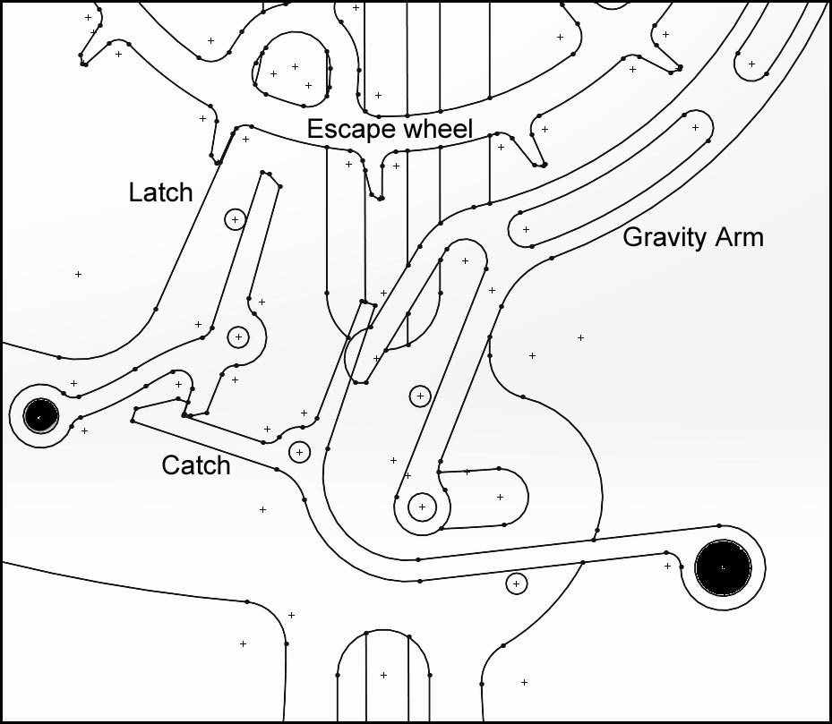 This is the concept laid out in 2D CAD, it actually looked quite promising at this stage, but later analysis showed that the latch would be pushed around so far before it could release the Escape wheel that the was a god chance it would not get back again before the next tooth arrived.
Time for a re-think, we need the latch to return much more quickly and with more certainty so its time to try a latch with multiple teeth.

This gives you an idea of the way I'm thinking but it needs more resolution how it is to interact with the Gravity arm

This is starting to look more promising, with multiple arms on the latch, one will always be in position to catch the next tooth.

Transferred into 2D CAD it was found that 5 arms on the latch would be optimum for this arrangement, so it is this concept was moved into 3D CAD and animated.
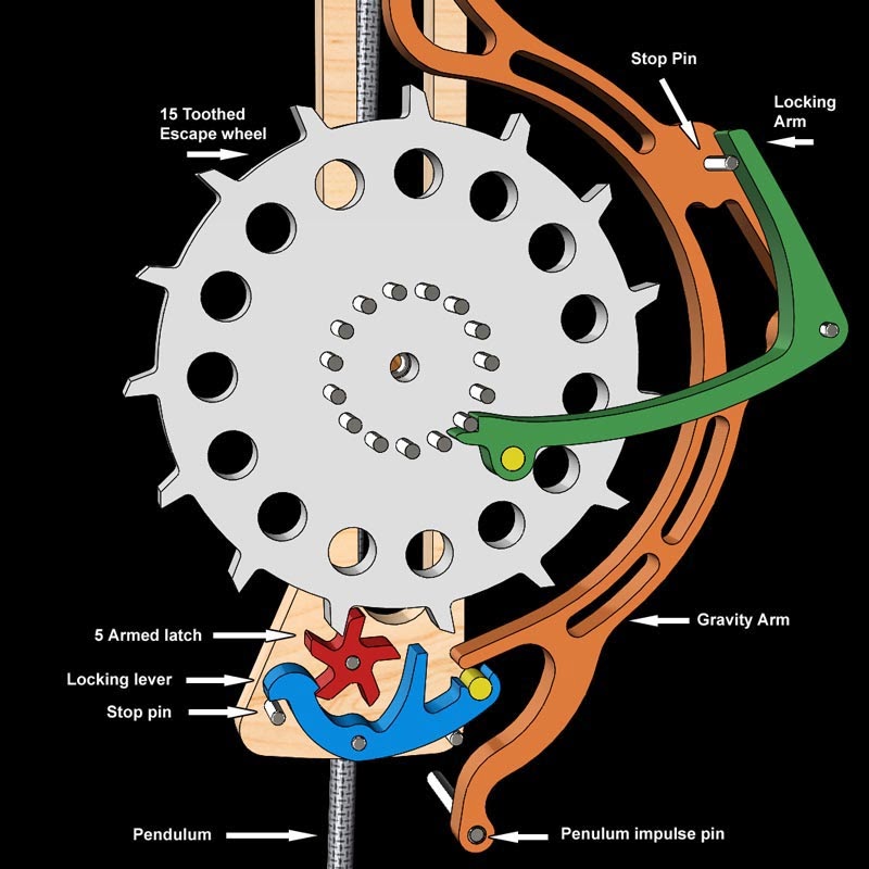
In this design the red Five armed Latch holds back the white Escape wheel whilst being held itself by the blue Locking lever. This is released by the Gravity arm after it has been released by the Pendulum at the end of its anti clockwise swing, the Gravity arm now swings down carrying the Pendulum with it, it hits the blue Locking lever releasing the red 5 armed Latch to allow the Escape wheel to run free, pushing on the green Locking arm to reset the Gravity arm.
The pendulum plays no part in this unlocking, only the Gravity arm.
The red Five armed Latch rotates to bring the next locking face into play before the next tooth on the Escape wheel can get past, the Five armed latch in the meantime is itself locked by the return of the blue Locking lever under the influence of gravity, assisted by the brass weight positioned at the back of the locking lever.
http://youtu.be/Jndb4gSwWvw
I have shown below some of the ideas from my sketch book, these were jotted down over a couple of days, this first one starts with a trigger mechanism used on a crossbow, it is capable of holding back high loads but is easily triggered, which is just what we need.
This sketch has the latch moved to the bottom of the escape wheel which is more convenient for picking up the end of the Gravity arm.
Time for a re-think, we need the latch to return much more quickly and with more certainty so its time to try a latch with multiple teeth.
This gives you an idea of the way I'm thinking but it needs more resolution how it is to interact with the Gravity arm
This is starting to look more promising, with multiple arms on the latch, one will always be in position to catch the next tooth.
Transferred into 2D CAD it was found that 5 arms on the latch would be optimum for this arrangement, so it is this concept was moved into 3D CAD and animated.
In this design the red Five armed Latch holds back the white Escape wheel whilst being held itself by the blue Locking lever. This is released by the Gravity arm after it has been released by the Pendulum at the end of its anti clockwise swing, the Gravity arm now swings down carrying the Pendulum with it, it hits the blue Locking lever releasing the red 5 armed Latch to allow the Escape wheel to run free, pushing on the green Locking arm to reset the Gravity arm.
The pendulum plays no part in this unlocking, only the Gravity arm.
The red Five armed Latch rotates to bring the next locking face into play before the next tooth on the Escape wheel can get past, the Five armed latch in the meantime is itself locked by the return of the blue Locking lever under the influence of gravity, assisted by the brass weight positioned at the back of the locking lever.
http://youtu.be/Jndb4gSwWvw
The next step is to build a prototype to ensure that the design really does work, and if that is successful incorporate the design into a clock.
Brian, looks brilliant and challenging. Cant wait for the clock design to be published.
ReplyDeleteAbraham Snir
like!
ReplyDeleteExcellent
ReplyDeleteExcellent
ReplyDeleteAlso, how easy is it to change a blade? Is a tool required for this? Some scroll saw projects have hundreds of holes. best pole saws 2020
ReplyDeleteso, does it work?
ReplyDelete